How to maintain quality of electric pump and motors
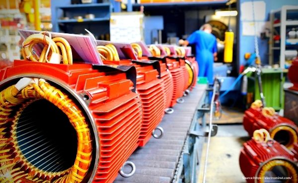
Problem Faced by Pump and Motor manufacturer
The most perplexing question for Electric pump and Motor manufacture is to maintain the quality of electric pump and motors and it’s replacement under warranty, as it effects to productivity, Profit margins, Customer loyalty, business partner’s trust, a Confidence level of entrepreneurs, Work culture, Relationship with vendors.
Reason for Problem in Pump and Motor
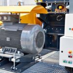
There are many causes of failure of motors, One of the most common of these causes is testing of motors if it is not according to accepted standards. Due to which motors underperform during actual application. This leads to rise in the probability of motor failure.

How to Cope up with this problem
To avoid this type of failure motors, need to be tested according to the accepted standards.
As per BIS standards routine test of motors is mandatory for each motor.
Routine test of motors is important as it allows us to know if there is any deviation in raw material or Human errors which may affect the quality of a product.
| List of Various BIS Standard For Routine Test of Electric Pump | ||||
| IS 8034 :2018 | IS 9079 : 2018 | IS 8472 :2018 | IS 12615 :2018 | IS 14220 : 2018 |
| a) Insulation resistance test (Before high voltage test only) | A) High voltage test; | a) Insulation resistance Test (before high voltage test) Ref.: 16.3 (a) IS 14582 | a) 16.1.1 Insulation Resistance Test The tests shall be carried out as given in IS 7816. The minimum value of insulation resistance shall be 30 MΩ | a) Insulation resistance Test (Both before and after the high voltage test) (Ref: 9.2 of. IS8034 , One sample of each identical type and design (Out of every 100 Pump sets or every month whichever is earlier) |
| b) High voltage test; | b) Insulation resistance test; | b) High Voltage Test Ref.:16.3 (a) IS 14582 | b) 16.1.2 Measurement of Resistance of Windings of Stator The method of measurement and the requirement shall be as given in 8.6 of IS 15999 (Part 1) and 5.7 of IS 15999 (Part 2/ Sec1) | b) High voltage test; |
| c) No load running of motor and reading of current, voltage, power and speed; and | c) Test for no load current and power input at rated voltage and supply frequency | b) High Voltage Test Ref.:16.3 (b), IS 14582 | C) 16.1.3 No Load Test The tests shall be carried out as given in IS 15999 (Part 2/Sec1) and 9.1 of IS 15999 (Part 1)/IEC 60034-1 (see note). NOTE— the no-load current and no-load power input values when motor is at temperature stabilized condition and when motor is at ambient temperature, will vary. However, these values may be obtained only from routine test certificate of the motor. | c) No load running of motor and reading of voltage current, power input and speeds; |
| d) Locked rotor reading of voltage, current and power. The requirements and values shall be in accordance with those speci ed in IS 9283 as may be applicable | d) Locked rotor test for locked rotor current, power input at a suitable voltage and supply frequency | c) Test for no load current, power input and speed at rated voltage & frequency Ref.: 16.3 (c), IS 14582 | D) 16.1.4 Locked Rotor Readings of Voltage, Current and Power Input at a Suitable Reduced Voltage The test may be carried out at reduced voltage. | d) Locked rotor reading of voltage, current and power and torque of motors; |
| e) Reduced voltage running up test shall be conducted at a voltage not exceeding 75 percent of voltage in case of single phase monoset and 60 percent of the rated voltage in case of three-phase monoset to check the ability of the motor to attain full speed. NOTE — In case of three-phase motor for monosets, the value of the current (amperes) shall be the average value of currents (amperes) measured in all the three phases. The requirements and values shall be in accordance with those speci ed in IS 7538 or IS 14582 as may be applicable. | d) Locked rotor reading of voltage, current and power input at a suitable reduced voltage Ref.: 16.3 (d), IS 14582 | E) 16.1.5 Reduced Voltage Running up Test at no-load (for squirrel cage motor up to 37 kW only) The test is conducted to check the ability of the motor to run up to its rated speed at no load. The motor shall be supplied with reduced voltage 1/√3 of rated value for each direction of rotation. | e) Reduced voltage running up test at no load to check the ability of the motor to run up to full speed on no load with 60 percent of the rated voltage applied to the motor for three phase motors and 75 percent of the rated voltage applied to the motor for single phase motors; | |
| f) 16.1.6 High Voltage Test The tests shall be carried out as given in 9.2 of IS 15999 (Part 1) (see Note) NOTE— the leakage current drawn by the motor during high voltage test, will vary depending upon frame size, power, insulation and polarity of the motor. This test may be conducted only once at full stipulated voltage. Subsequent tests must be conducted at 80 percent voltage of the previous test. | ||||
Insulation resistance test
It is also known as Megger test. (Megger is brand).
An insulation resistance (IR) test measures the total resistance between any two points separated by electrical insulation.
The test, therefore, determines how effective the dielectric (insulation) is in resisting the flow of electrical current Insulation resistance quality of an electrical system degrades with time, environmental conditions i.e. temperature, humidity, moisture, and dust particles.
Procedure:
A DC voltage (500Vdc) is applied to the winding and the frame to which the magnetic circuit and other windings are connected. In the case the stator capacitance is too high for the instrument the measurement can be performed phase by phase neutral open. For main windings, this measurement is performed twice, before and after the dielectric test.
The measured resistance values need to be verified against acceptance criteria provided in the test procedure.
As per IS standard minimum 5 megaohms Insulation resistance required.
High voltage test
High Voltage testing is usually performed to qualify the device to operate safely during rated electrical conditions, a way to check the effectiveness of its insulation.
The objective sought during the high voltage testing will determine the type and amount of voltage applied and the acceptable current flow. Normally Voltage given during high voltage is 2 X rated voltage + 1000 Volt for the first time. If you do it again it should be 80% less than the previous voltage.
Winding resistance test
The purpose of this test at induction motor testing is to measure the resistance of stator, rotor, and exciter windings to ensure that the values calculated at 20°C (ambient) conform to the technical specifications.
These values are used for the calculation of temperature rise. The resistances are measured by the Voltammetric method at ambient temperature. The test is performed by a current generator and a voltmeter.
The acceptance criteria shall be based on the manufacturer-approved procedure but usually phase to phase deviation should not be more than 2%, and max deviation from theoretical value should not be more than 5%.
No load test
No Load Test is an indirect method used for determining the efficiency and also to determine the circuit parameters of the equivalent circuit of the three-phase induction motors.
The open circuit test performed on the transformer. No load test is same as the open circuit test performed on the transformer.
Reduced voltage test
This test is done to see the performance of motor is same for both directions or not.
Reduced voltage running up test shall be conducted at a voltage not exceeding 75% percent of voltage in case of single-phase motors and 60% percent of the rated voltage in case of three-phase motors to check the ability of the motor to attain full speed.
Locked Rotor test
A locked rotor test is normally performed on an induction motor to find out the leakage impedance.
Apart from it, other parameters such as torque, motor, short-circuit current at normal voltage, and many more could be found from this test. The blocked rotor test is analogous to the short circuit test of the transformer.
Leakage Current test
The objective of the Leakage Current test is to verify that the electrical insulation used to protect the user from a Risk of Shock is suitable for the application.
During any electrical installation, some current will flow through the protective ground conductor to the ground. Leakage current most commonly flows in the insulation surrounding conductors and in the filters protecting electronic equipment around the home or office.
How we can help you
Aarohi introduced fully automatic routine test panel.
The primary purpose of the routine test is to ensure freedom from electrical and mechanical defects and to demonstrate by means of key tests the similarity of the motor to a “standard” motor of the same design.
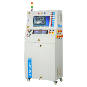
This panel also help to enhance productivity, Work efficiency & reduces the need for skill operator.
| FEATURES | BENEFIT |
| Automatic data logging facility | Minimize human efforts & errors |
| Model/ Motor wise report generation | Provide production data analytics |
| Clint server based software | Any one can access easily on network |
| Voltage controlled by multi tapping transformer/ Motorised operation | Reduces testing cycle time.. |
| Aesthetic design of panel | Create a good imprecation on visitors |
| Software with user management | Avoid unauthorised usage. |
| Store each & every test result | Data analytics possible |
| Automatic tolerance selection from database | Avoid dependency of highly slick person |
| My sql database | Easy to sink data with ERP OR SAP. |